 dsale@topsfp.com
 русский
 English
 español
 العربية
 中文
中文



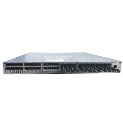
Fiber Optic Patch Panels: Selection, Installation, and Maintenance Guide
A fiber optic patch panel is an organized termination and cross-connect point for fiber cabling. It is not simply a device that joins two connectors. In a structured cabling system, the panel provides a protected, labeled location where incoming cables, splices, adapters, and patch cords can be managed. Used well, it makes a network easier to install, test, expand, and troubleshoot. Used poorly, it can become a source of congestion, contamination, undocumented changes, and difficult fault isolation.
Patch panels are used in data centers, enterprise equipment rooms, telecom environments, campus networks, and building backbones. The right design depends on the number of fibers, connector format, cable route, equipment density, future growth plan, and maintenance practices. This guide explains the main decisions to make before selecting or installing a fiber optic patch-panel system.
What a patch panel does
A typical panel houses adapters or cassette modules that present accessible ports on the front and terminate, splice, or route the permanent cable on the rear or inside the enclosure. Patch cords then connect the front ports to active equipment such as switches, routers, servers, storage systems, or optical transport platforms. The panel separates the more permanent cabling from the flexible equipment connections. This reduces stress on backbone cable and allows moves, adds, and changes to be completed at a documented connection point.
The panel may also provide splice trays, cable-entry management, strain relief, grounding where required, slack storage, dust protection, and labeling space. The exact combination varies by enclosure and cabling design. An adapter inside a panel couples compatible connectors; it does not change the optical type or make incompatible systems work together. The connected fiber, connector polish, polarity, and optical interfaces still need to match the intended link.
Choose the enclosure type for the environment
Rack-mount patch panels are common in data centers and equipment rooms. They may be fixed, sliding, or high-density chassis designs. Wall-mount enclosures are often used for building entrances, telecom rooms, floor distribution, and smaller network locations. Outdoor or industrial environments may require enclosures with additional environmental protection. The choice should account for the available mounting space, access direction, cable-entry method, service clearance, and the expected number of future connections.
Do not size the panel only for the number of ports required today. Consider practical expansion space, cable routing, adapter or cassette capacity, and the room needed to service the rear of the enclosure. Overfilling a panel can make fiber management difficult and increase the risk of bends, connector contamination, or accidental disconnection. A phased design with documented spare capacity is usually easier to maintain than a fully packed enclosure with no service margin.
Connector and fiber choices must match the link
Patch panels can support many connector families, including LC, SC, FC, ST, MPO/MTP, and other specialized interfaces. The correct choice is determined by the cable plant and the active equipment, not by appearance alone. LC duplex interfaces are common in many Ethernet and Fibre Channel connections, while MPO/MTP-style interfaces are used in parallel-fiber and high-density applications. The connector’s polish type, such as UPC or APC, is also important. These types should not be mixed without an approved design because their physical interface and optical behavior differ.
Fiber type matters just as much. Single-mode and multimode fiber serve different reach and wavelength requirements. Within each category, the grade and condition of the installed fiber can affect which optics and applications are appropriate. Before selecting a panel, adapter, cassette, or patch cord, document the existing fiber type, connector type, polarity method, and planned optical interfaces. This information should appear in the bill of materials and the installation drawing.
Polarity and cassette planning
Fiber polarity ensures that a transmitter at one end of a link reaches the receiver at the other end. In duplex links, the transmit and receive paths must be crossed correctly. In parallel-fiber systems, lane mapping is more complex and must follow the selected method and equipment documentation. Patch panels and cassettes can support different polarity strategies, so it is essential to define the method before purchasing components.
A common mistake is to select cassettes and trunks from different systems without verifying the end-to-end mapping. The result may look physically complete but fail to bring up the intended link. Create a topology drawing that identifies every segment: active port, patch cord, front adapter, cassette, trunk cable, rear connection, remote panel, and receiving port. Review the polarity at each stage and test the finished channel before production use.
Installation and cable management
Good installation practices protect the optical path. Observe the fiber manufacturer’s minimum bend radius and pulling limits. Use proper strain relief at cable entries. Keep patch cords routed through designated management rings or guides rather than draped across equipment. Avoid closing a sliding tray on a fiber path that has not been checked for clearance. Make sure that labels remain visible after patching changes.
Connector cleanliness is critical. Inspect and clean connectors using approved procedures before mating them. Protect unused adapters with suitable dust caps. Do not assume a connector is clean because it looks clean to the eye. Contamination can increase loss, create intermittent errors, or damage a mating surface. When a panel is serviced, clean work habits and careful handling help preserve the reliability of the whole system.
Labeling, documentation, and testing
A panel is only as useful as the information associated with it. Label each enclosure, slot, adapter, cassette, and port using a consistent scheme. Keep a record of the cable route, fiber type, connector type, port assignments, link purpose, and test results. In a larger environment, these records should connect to the rack map and network documentation so that a technician can identify both ends of a link without guesswork.
After installation, test the link according to the project requirements. This may include continuity and polarity checks, insertion-loss testing, optical time-domain reflectometer testing where appropriate, and active-equipment link validation. Record the baseline results. When a future issue appears, the baseline helps distinguish a new fault from a pre-existing condition and reduces the time needed to isolate the problem.
Planning for changes
Networks change. New servers, switches, storage platforms, and applications may require additional fiber paths or different port densities. A well-planned patch-panel system supports these changes without disrupting existing links. Reserve capacity where practical, standardize the chosen connector and cassette families, and keep spare parts that match the installed system. Before making a change, update the drawing, confirm the polarity, plan the work window, and test the result.
Conclusion
Fiber optic patch panels provide the structure that makes a cabling system manageable. The best results come from selecting the enclosure, adapters, cassettes, connectors, and fiber types as one end-to-end design. Define the link requirements, plan polarity, protect the fiber during installation, keep the system clean and labeled, test the completed path, and maintain accurate records. With these practices, a patch panel becomes a reliable foundation for current connectivity and future expansion.
